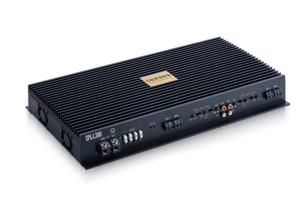
- BEESES
Meet the Purest Sound
Experience Music in its Naturalness: Honeycomb Model Amplifier,
it presents the sound in its most natural and simple form. If you want to hear music as it is, this is the amp to choose. No excesses, no coloration, just pure sound!


In Control, Enjoy the Music
Simplicity and Easy Operation: Honeycomb Model Amplifier,
makes it easy to just listen to your music, without fiddling with complicated settings. Simplicity and ease of use
is a preferred option.
The True Power of Sound is Here
Clear and Natural Sound Performance: Honeycomb Model Amplifier,
to transmit sound without losing any detail
designed. You can hear the music as it is and admire each note individually.

Connection Settings
1. GND
Chassis connection (battery negative terminal or metal body of the vehicle).
Remote (Rem)
The remote cable, usually blue in color, allows the amplifier to receive a remote on or off signal. It may also be labeled "REM" or "REMOTE". This cable is used when installing a car stereo system or when mounting an amplifier.
+ 12 V
+12V Battery positive terminal connection for power output cable.
2. 4X25A FUSE
The 100A fuse in the amplifier is a safety device that protects against overcurrent or overload. If the amplifier encounters dangerous situations such as an abnormal electrical load or a short circuit, the fuse works to prevent or limit these situations. In this way it ensures the safety of the amplifier and connected equipment.
3. POWER AND PROTECH LEDS
LEDs that light up when the amplifier is activated indicate normal operation. LEDs that come on when the amplifier is in protection mode indicate problems such as overload, low voltage or high temperature.
Output and Crossover Settings
4. CONNECTION TERMINALS
LR1/2 Speaker connection terminals of the output stage.
5. LR1/2 GAIN
In amplification, "gain" is a control parameter used to increase or decrease the sound. Adjust the gain according to the technical parameters of your speaker. If you turn the gain too high, your speaker may be damaged.
CROSSOVER SETTINGS
It allows your amplifier to drive different frequency ranges. There are three main types of settings:
- Low-pass crossover: It is a filter that passes only low frequencies (bass sounds). This setting is ideal for subwoofers.
- High-pass crossover: It is a filter that passes only high frequencies (treble). This setting is preferred for tweeters.
- Band Pass Crossover: A filter that passes a specific frequency range (both low and high). It is often used for mid-range speakers.

+ 12 V: +12V Battery positive terminal connection for power output cable.
Remote (Rem): The remote cable, usually blue in color, allows the amplifier to receive a remote on or off signal. It may also be labeled "REM" or "REMOTE". This cable is used when installing a car stereo system or when mounting an amplifier.
GND: Chassis connection (battery negative terminal or metal body of the vehicle).
4X25A Fuse: The 100A fuse in the amplifier is a safety device that protects against overcurrent or overload. If the amplifier encounters dangerous situations such as an abnormal electrical load or a short circuit, the fuse works to prevent or limit these situations. In this way it ensures the safety of the amplifier and connected equipment.
Minimum Impedance 2 Ohms: Make sure the polarity of the speakers is connected correctly. Otherwise, the speakers may cancel each other out due to the reversed phases and sound loss may occur. This will negatively affect your music experience and reduce the quality of the sound. Also note that the minimum impedance of your speakers is 2 ohms; if it falls below this value, it can damage the speakers.
In amplification, "gain" is a control parameter used to increase or decrease the volume.
- Adjust the gain according to the technical parameters of your loudspeaker. If you turn the gain too high, your speaker may be damaged.
- It is important to set the crossover cutoff settings correctly, taking into account the operating frequency ranges of the speakers. Each loudspeaker performs best at certain frequencies; incorrect settings can damage the loudspeakers by causing sound distortion, distortion and overload. Proper settings improve sound quality and ensure the durability of the equipment. For this reason, it is critical to set the appropriate cutoff settings for the frequency ranges of the loudspeakers.
Technical Specifications
| Feature | Value |
|---|---|
| Operating Voltage | 10.5 V - 18 V |
| Output Power RMS / Max | - @ 4 Ohm: 4 x 200 Watts - @ 2 Ohm: 4 x 380 Watts |
| THD | % 0,03 % 0.8 (4×200 W 4 Ohm Full load) |
| Dumping | 400 |
| S/N Ratio | 110 dB |
| Input Sensitivity | 0,2 - 10V |
| Frequency Range | 12 - 32,000 Hz |
| Dimensions | 435 x 215.3 x 62.2 mm |
| Weight | 5650 gr |
| Amplifier Technology | Class AB |
Journey to Excellence
Feed Solid
The original and high quality components chosen for our supply circuitry have increased the energy efficiency of our class AB amplifier to the same level as digital amplifiers. The most important components have been carefully selected to ensure low energy consumption and high quality sound power.
In this design, 2 1.5 kW transformers and 8 IR power MOSFETs driving these transformers were used. The outputs of the transformers are connected in parallel. Distortion is minimized by line filters.
In order to compensate for the overcurrents drawn under load, 6 Nichicon brand 125℃ Low ESR automotive series capacitors capable of instantaneous high current were preferred.
18 VISHAY brand 105℃ Low ESR high amperage capacitors were used to minimize the current to be drawn from the grid.
Protection/Cooling
In SPL amplifiers, amplifier failure is a common occurrence. Since low battery voltages, overloads, clipping and DC character caused by improper settings are much more common than in SQ systems, we have designed the protection circuits in our SPL amplifiers very comprehensively.
There are 2 suction fans and 2 blowing fans adjusted according to the heat and power ratio. These four fans are activated when necessary. The fans are activated at instantaneous overload. In addition, there are drive circuits that continuously control the temperature and adjust the fan speed according to the temperature in case of prolonged operation of the amplifier (more than 4 hours). In the event of a temperature spike, such as when the fans are switched off, short circuit, overload or continuous low voltage supply, the amplifier will shut itself down until conditions improve.
There is current, voltage, heat and overload protection for each channel individually and clip, heat and reverse voltage protection for the entire amplifier.
The fuses will blow in the reverse voltage connection ("+" and "-" 12 Volts). After correcting the faulty connection and installing new fuses, the amplifier can be used again.
Output Stage Protection Circuits
Each of the 4 output circuits inside the amplifier has several protection circuits of its own. There are output relays that control each output separately. These relays both protect the loudspeakers in case of a malfunction in the amplifier and protect the amplifier in case of a problem with the connection and the loudspeakers.
The output stage protection circuits do not affect each other; they operate independently.
The protection circuit of the output stage is activated in the event of clip (clipping, DC), overload, short circuit and external power input. In special cases, such as external power entering the speaker connection or the live end of the speaker touching the car body, the amplifier output may be damaged. In this case, the protection circuit switches off the relay output and also switches off the amplifier supply, ensuring safety.
Output stages (amplifiers)
- The amplifier uses VISHAY's TO247 sheath MOSFET transistors, which offer high power. Thanks to the use of six MOSFETs in each output, each channel performed smoothly even when tested with 600 watts under 1 ohm load.
- The use of more powerful components than necessary in the supply and output stages ensures that our amplifier operates smoothly and efficiently without generating excessive heat. Although operation under a 1 ohm load was performed in the test environment, the 1 ohm operating limits of the released model are restricted.
- The output stages are driven by matched TOSHIBA custom audio amplifier transistors, with TOSHIBA transistors from the same series supporting the output power transistors. Original materials from the best manufacturers are used to produce SPL-level SQ amplifiers. This design has been meticulously crafted to maximize performance and durability.


 E-Mail: